This topic describes relevant information about TYLC4 module during MCU connection development.
For more information, see Wi-Fi module introduction — TYLC4.
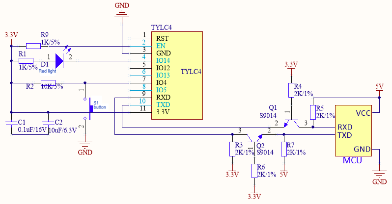
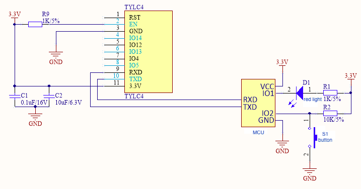
Figure 1 and Figure 2 are typical application diagrams of self-processing mode of TYLC4 module and MCU connection. Figure 3 and Figure 4 are typical application diagrams of coordinated processing mode of TYLC4 module and MCU connection.
S1 is a reset button of the Wi-Fi module, and LED1 is a status indicator light of the Wi-Fi module. The following table shows the relation between LED1 status and Wi-Fi module working status.
| LED1 status | LED1 display | Working status of Wi-Fi module |
|---|---|---|
| Flicker fast | On and off interval is 250 ms | Fast connection mode (Smartconfig mode) |
| Flicker slowly | On and off interval is 1,500 ms | Compatible mode (AP network configuration mode) |
| Always on | Always on | Wi-Fi module is connected to the router |
| Always off | Always off | Wi-Fi module is disconnected from the router |
Figure 1 is a reference diagram of self-processing mode of the module and 5V MCU communication.
Figure 2 is a reference diagram of self-processing mode of the module and 3.3V MCU communication.
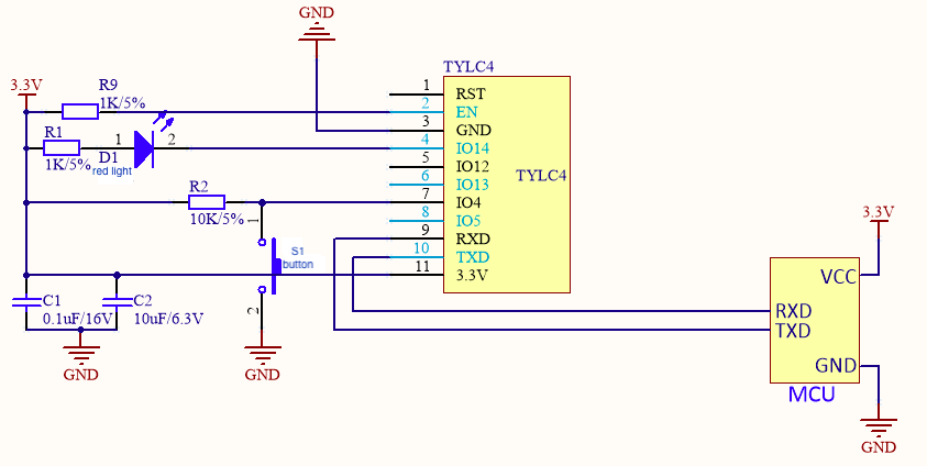
Figure 3 is a reference diagram of coordinated processing mode of the module and 5V MCU.
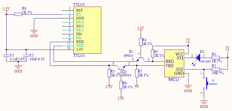
Figure 4 is a reference diagram of coordinated processing mode of the module and 3.3V MCU.
Module power supply:
Power consumption during normal work: 3.3V/100mA. For a 3.3V module, recommended supply current is ≥ 300mA. Total capacitance value of external filter capacitor is greater than 10uF. When the 3.3V module is sending or receiving RF, the current increases by 50%.
In the PCB layout, power filter capacitors C1 and C2 at the power input pin shall be arranged near the VCC pin.
Module pin:
Serial ports TXD and RXD are connected to your MCU. Default settings are as follows. Baud: 9600, data bit: 8 bits, stop bit: 1 bit, no check bit, and no flow control. During power-on of the module, TXD pin prints some start information of the module. You can neglect the printing information of the serial port during this period. If you need to use this serial port as a general I/O port, contact R&D personnel of this company.
RST pin can reset the module hardware. It is valid in case of low electrical level. To use the RST pin, connect it to I/O port of MCU. Make sure that the electrical level is matched.
If required, the module can be connected to a button and a Wi-Fi status indicator light.
Pins not in use can float.
Radio frequency (RF) of the module: