This topic describes the wiring and radio frequency (RF) design of Wi-Fi smart door lock modules and the design of TYWE1S and XR1 modules.
Wi-Fi smart door locks support the following modules: TYWE1S, XR1, XR3, and XR1-IPEX. For more information, see TYWE1S Module Datasheet, XR1 Module Datasheet, and XR3 Module Datasheet.
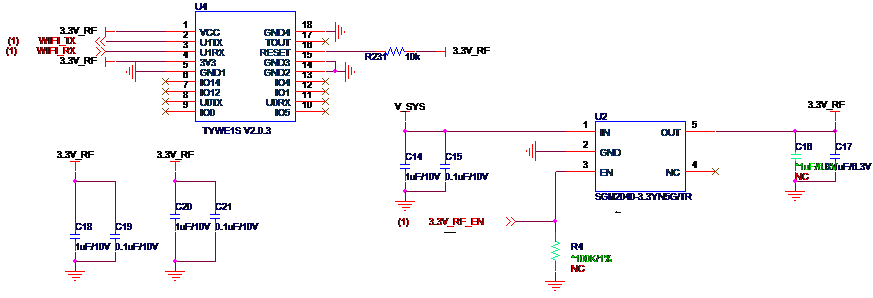
The following figures show the Wi-Fi schematic design of non-Wi-Fi keep-alive smart door locks.
The E1S and XR1 Wi-Fi modules provide the following ports for smart door locks: the 3.3V power supply and universal asynchronous receiver-transmitter (UART) user serial port. When you design a smart door lock, you must consider the power supply control for the module. We recommend that you select a low quiescent current (IQ) low-dropout (LDO) voltage regulator or a DC/DC switching regulator. In the standby status, to ensure low power consumption, the Wi-Fi power supply must be turned off.
The Wi-Fi modules E1S and XR1 provided by Tuya apply to smart door locks. However, the metal structure of smart door locks might have an impact on the RF performance of antennas. Therefore, in the early structural design, the location and overall structure of an antenna must be optimized to minimize the impact on the RF performance. For more information, see TYWE1S Module Datasheet, XR1 Module Datasheet, and XR3 Module Datasheet.
Note:
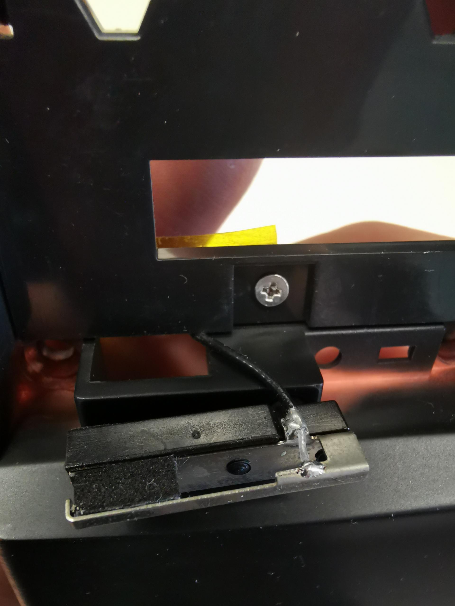
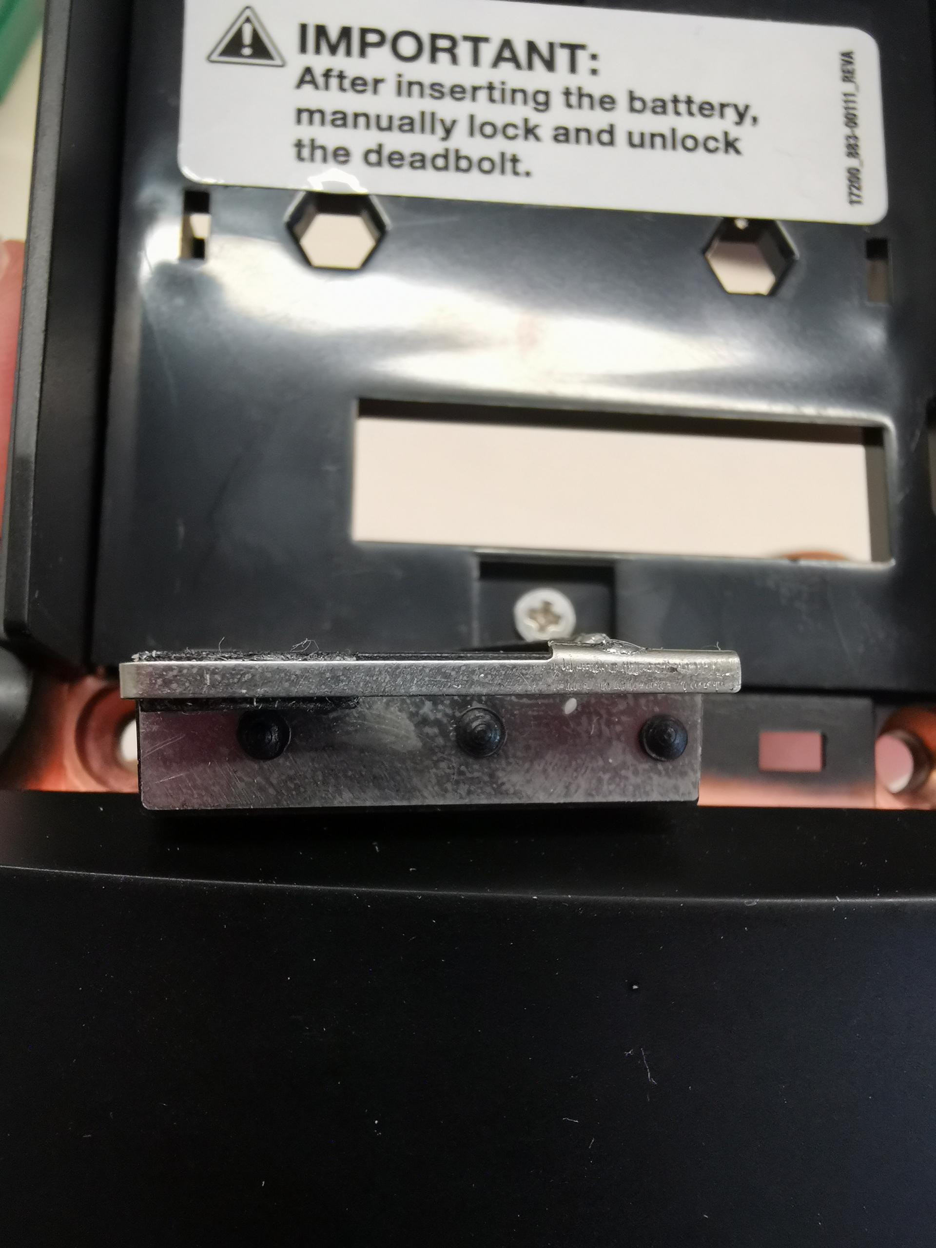
- Make sure that the metal components such as the substrate medium and lock are not located below or above the printed antenna.
- Make sure that the printed antenna is away from the copper sheet to maximize the radiation effect of the antenna.
An onboard antenna provides limited performance for a module. We recommend that you use an external antenna if conditions permit.
Examples:
Stick the antenna on a non-metal shell
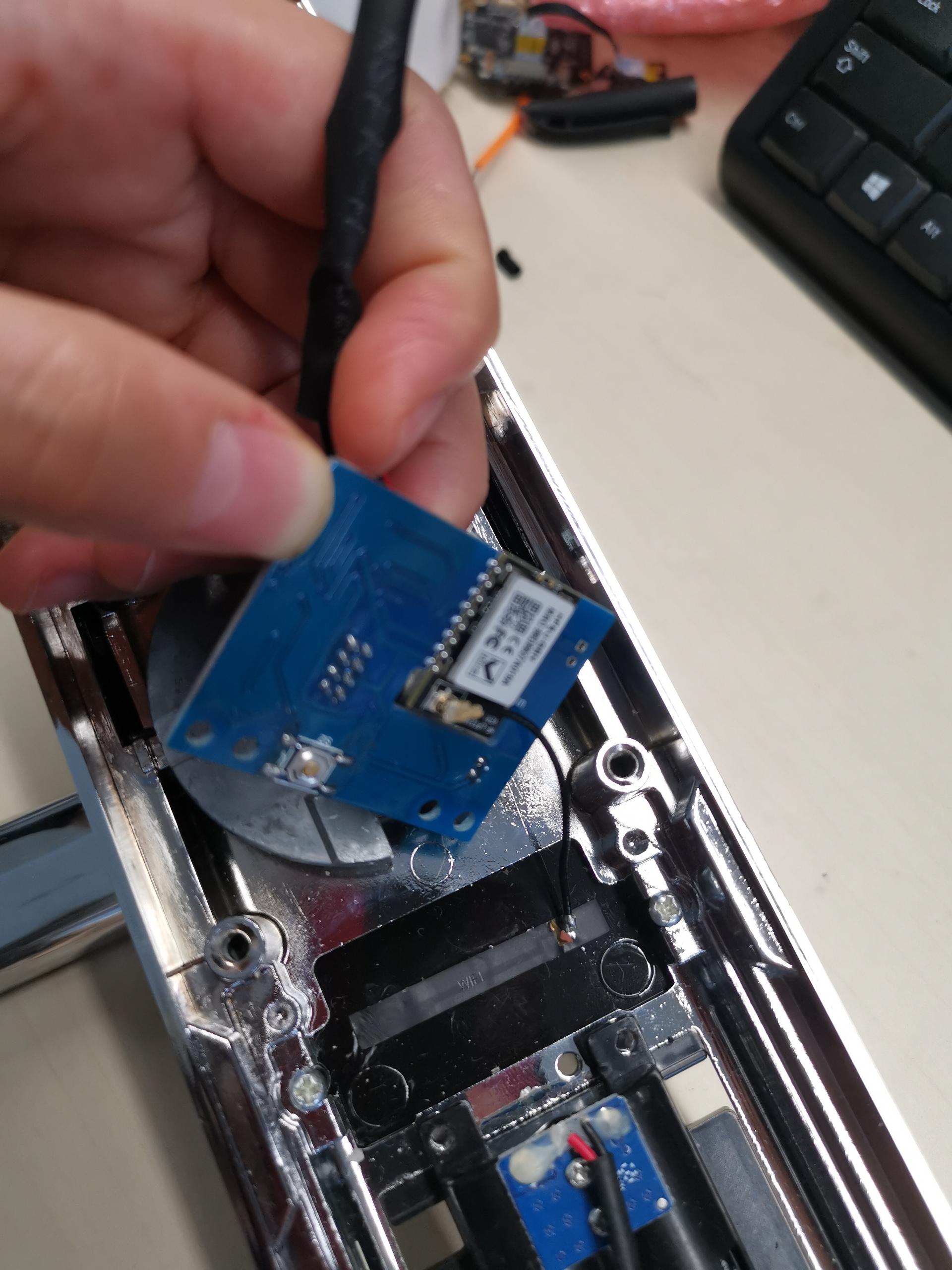
Use an antenna bracket